Mechanical clamping of press-pack high power semiconductors
Press-pack high power semiconductors are in many applications very powerful components in controlling electrical power. To utilise their full potential a proper mechanical design of the complete assembly, including press-pack high power semiconductors, heat sinks,bus bars and other components, is crucial. In this application note some important issues for the mechanical design and the assembly work for stacks using press-pack high power semiconductors are addressed.


1. Recommendations for the interface properties
The current and heat conducting interfaces should be designed to retain good conduction properties throughout the equipment lifetime. This is accomplished by creating a sufficient number of stable
metal-to-metal connections, referred to as «a-spots» in contact theory, which can efficiently conduct current from the semiconductor through the heat sink to the bus bars. These a-spots must be maintained during hard stress conditions such as load cycling,vibration and chemical contamination such as sulphur gases. To achieve this, care must be taken in choosing the right materials for the components. They must be coated properly and have the right surface finish. In this application note we concentrate on the interface between the press-pack high power semiconductor and the heat sink.
1.1. Definitions

Roughness: The surface roughness is a measure of the microstructure of the surface. It is expressed as an Ra-value as per ISO 4287. The roughness is Ra < 0.8 micrometer for all Hitachi Energy semiconductor press-pack devices.
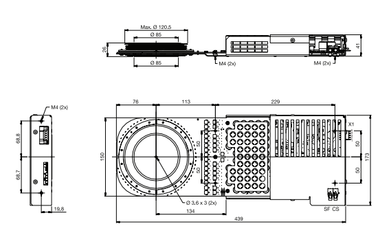
Flatness: The flatness is < 10 µm for Hitachi Energy devices with pole piece diameter < 50 mm and < 15 µm for Hitachi Energy devices with pole piece diameter > 50 milimeters. This means that Application Note 55YA2036-04 a specific pole piece surface is limited by two parallel planes at a maximum distance of 10 or 15 µm apart.
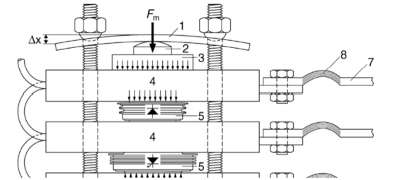
FM: The mounting force is the recommended force to be applied for optimal device performance. The data sheet limits are not guaranteed at too low a mounting force. The thermal impedance and the on-state voltage drop will increase, and the surge current rating will decrease when the force is reduced below the rated value. Too high a mounting force may reduce the load cycling capability by excessive deformations of the fine wafer structures or, at worst, by silicon wafer cracks.

1.2. Design of the utilised components
When using water-cooled heat sinks the cooling should be as homogeneous as possible over the entire contact surface of the device. A single water channel through the centre of the heat sink
may not be sufficient for heavy-duty equipment and could lead to overheating of the device rim. It is advisable to use water channels that create turbulences rather than using simple straight paths(though this may be sufficient for light duty units).
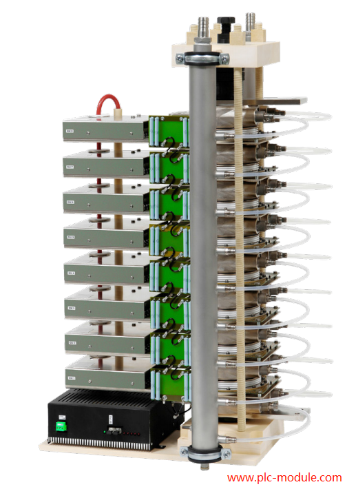
Hitachi Energy supplies compact water-cooled heat sinks for heavy-duty equipment see Figure 1. These heat sinks use a stainless steel spiral tube on both sides of the surface to optimize cooling. For more information about heat sinks see the contacts in section 4.2.

2.Recommendations for assembly(www.plc-module.com)
Even the best of designs will not lead to the intended result if the stack is not assembled correctly. In this section some issues of importance for the assembly work are described. Before assembly, the contact surfaces must be thoroughly cleaned using ethanol (or similar solvent) and a lint-free cloth. The assembly should be carried out in a clean environment free of dust and humidity as the surfaces must be kept clean during the whole assembly procedure. Heat sink and semiconductor surfaces should not be touched with bare hands. We recommend the use of lint-free gloves for the handling of semiconductor devices and heat sinks. The heat sinks and press-packs should be handled with care to avoid scratches and other damages to the surfaces. Small scratches should be avoided (even though they are not detrimental to contact integrity since it is the overall surface finish which determines contact quality). The surface finish must remain within the specification given earlier


More...