BENTLY ORBIT 60 SERIES System Bently Nevada Machinery Condition Monitoring
BENTLY ORBIT 60 SERIES System Bently Nevada Machinery Condition Monitoring
Initial release supports 48 dynamic channels with 1 chassis
Plant-wide • One System
The Orbit 60 Series Protection and Condition Monitoring System provides one continuous, online monitoring system for both critical and plant-wide applications.
Cyber Secure • Data Isolation
Orbit 60 Series data isolation creates a safe industrial data environment designed to meet ISA 62443 with world class network security features and segregation of protection and condition monitoring functions.
Modular • Flexible • Scalable
The Orbit 60 Series system is deployable in any combination of rackmounted and distributed hardware. This provides for better alignment of instrumentation to the machinery application.
High Speed Process Data Integration
Next generation architecture facilitates full bi-directional communications with plant control systems over a suite of standard protocols.
Extended Field Wiring Length
With the Orbit 60 Series distributed architecture, connection of multiple chassis through Bridge modules decreases overall electrical installation costs, reduces analog ground loops and noise issues, and moves key maintenance activities further from hazardous areas.
Industry Leading System Capabilities
The Orbit 60 Series supports monitoring of one or multiple machine trains in a single deployment. One System Interface Module (SIM) defines each system and can encompass up to 88 dynamic channels and 4 chassis* using Bridge modules to link them.
Overview
The Orbit 60 Series Protection and Condition Monitoring System provides a single platform for the continuous online monitoring of both critical and plant-wide applications. The Orbit 60 Series system is deployable in any combination of rackmounted and distributed hardware, with Bridge modules creating a seamless connection between chassis to make a single system.

SIM - System Interface Module
CMM - Condition Monitoring Module
CGW - Comm Gateway Module
BRG - Bridge Module*
S1 - System 1 Server or Client
CNFG - Orbit Studio Configuration Software
DCS/PLC - Distributed Control Systems/ Programmable Logic Controller
L1 - Unit Network
L2 -Control Network
L4 - Business Network
Figure 1: System Diagram
One System Interface Module (SIM) defines a system of up to 88 dynamic channels*, accommodating multiple machine trains and supporting unrestricted synchronous Keyphasors for any channel. The Condition Monitoring Module (CMM) interfaces to the business network through a cyber-secure access port. The Communications Gateway (CGW) sends(data, status, setpoints) and receives(inhibit, reset, trip multiply)* high speed process data with the control systems. Bridged (BRG) connections allow up to 3 chassis to act as a single system while decreasing overall installation costs, reducing ground loops, and minimizing electrical noise.
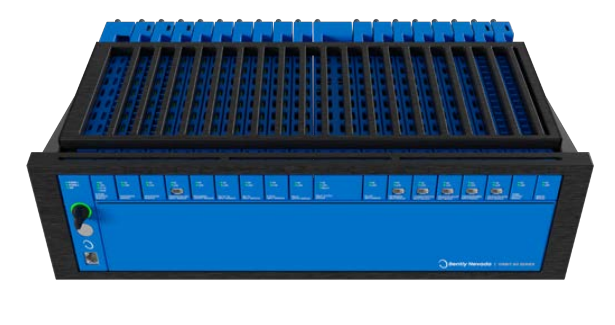
Orbit 60 Series Chassis
You can flexibly deploy each chassis option with a public facing side (for rack or panel mounts) and a utility side (for wiring connections and bulkhead mounts). Insert modules and make all wiring connections from the utility side. Provisions for the public side of the chassis include status LEDs, configuration port, Config/Run key, and reset button. Three chassis types are available.
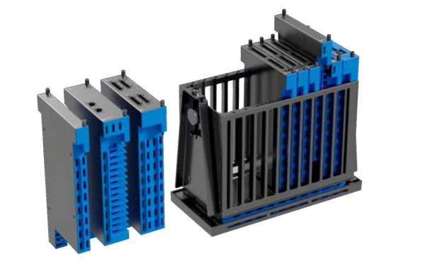
Chassis Types

Mounting Options
l Panel Mount – Mounts to rectangular cutouts in panels and secures to the panel using clamps supplied with the chassis in 3U Mini*, 3U 19" standard, and 6U 19" standard* configurations. The 6U 19" will fit in the space of a 3500 rack.*
l Rackmount – Mounts the 3U or 6U chassis on 19-inch EIA rails. Two 3U units or a single 6U* form factor have been designed to fit within the space of a single 19” rackmount 3500 unit, as a retrofit.
l Bulkhead - Typically mounts into a protective enclosure fastened to a sub panel in 3U Mini*, 3U 19" standard, and 6U 19" standard* configurations. NEMA 4 and 4X weatherproof housings are available when required for environmental protection or when purge air is used.
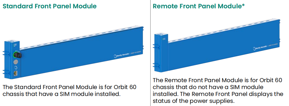
Front Panel Options There are two Orbit 60 Front Panel Module options.
System Interface Module

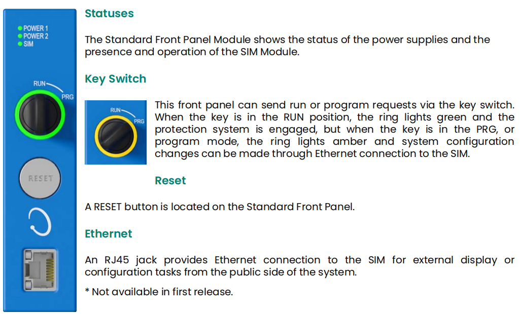
Each Orbit 60 system requires a single System Interface Module (SIM) The SIM provides the user access to manage protection configuration, local display, system-level diagnostics, system LEDs, system contacts, and the system protection fault relay. The SIM occupies one slot and must be adjacent to the Power Input Module (PIM) in the chassis.
The SIM is the access point for configuring and maintaining the system. The module communicates to the Orbit Studio configuration software and transmits the configuration to other modules in the system. The SIM provides a physical access security feature through a key-lock switch on the public side and a contact on the utility side of the SIM. Either of these controls can be used to secure the system configuration, preventing unauthorized changes.
The SIM has 3 independently configurable ethernet ports, each port can be used for system configuration, system time synchronization, temporary troubleshooting, or an external display.
Communication Gateway Module

The Communication Gateway Module (CGW) provides information to external hosts including measurements, alarms, statuses, and configuration information using standard industrial protocols. The CGW is designed to be used as part of a protection loop.
Through the Communication Gateway module, the system can acquire process data from external control systems, human interfaces, and data historians. The data can also be passed through to System 1. The Communication Gateway module occupies a single slot.
There are two versions of the CGW module:
• Serial* - RS-485 port supporting Modbus protocol*
• Ethernet - Two RJ-45 ethernet ports supporting Modbus and EGD* protocols
Protection Processing Module

The Protection Processing Module (PPM) serves as the computational engine for the Orbit 60 monitoring system. It extracts all machinery measurements for the protection system and performs alarm determinations. The PPM analyzes signals from transducers, generates measurements\statuses and publishes them to other modules for data collection and external communication. Each PPM occupies a single slot within the system.
Each PPM provides capacity for a large number of sensors and can support typical monitored machine trains. The PPM capacity is a function of the type of processing required on each input. If the system requires more processing than a single PPM can provide additional PPMs can be added to the system for complex monitoring deployments. . For protection systems, redundant PPMs are recommended.
The Orbit Studio Configuration Software provides a System Utilization Calculator to evaluate the remaining capacity of the PPMs in your system. If your processing capacity reaches 90%, a warning indicator displays and we recommend adding another PPM, or 2 PPMs if the system is redundant.
Condition Monitoring Module

The CMM listens to all information within the system, including all measurements, waveforms, digital transducer signals, system controls, status information, system configuration information, process data from external systems, and alarm and events logs. It only listens, with no capability to write, allowing interface to System 1 over the business networks, with no risk to the protection system.
Each module occupies two slots within the system. Placing multiple CMM modules allows the connection of two independent System 1 clients to the Orbit 60 System. Data is transferred to System 1 continuously, but in the event the connection is lost or System 1 is not utilized, non-volatile storage buffers historical data until the information is off-loaded to the host software. System 1 can configure the CMM module to extract additional measurements and waveforms from system sensor data.
Bridge Module (BRG)
")
The base-to-base Bridge module connects multiple chassis to make a distributed system. Bridge connectivity enables flexible deployments in linear or star topologies. The Orbit 60 System significantly reduces field wiring cost, especially when extending to remote locations. Each Bridge module communicates all data in the local chassis and replicates to the remote chassis. In this way, the system communicates all data within the system to all devices in the system.
The Bridge module provides protection from incompatible networks interfering with the operation of the system by blocking any transmissions from non�approved sources onto the chassis.
Power Input Module

The Power Input Modules (PIM) always reside in a special-purposed slot located in the first slot of the chassis. This slot accommodates two PIMs for redundancy. At least one PIM must power every chassis, and every chassis requires its own PIMs and power sources. Redundant PIMs and power sources are strongly recommended.
The PIM is a half-height module that connects an external power source to the system. Each Orbit 60 Series chassis supports two stacked redundant power input modules. Failure of one power source does not affect the operation if the system uses both power inputs. The PIM employs out-of-range protection for miswiring, overvoltage, and overcurrent protection for the input power sources.
The PIMs support input voltages ranging from +21 Vdc to +32 Vdc. The most common power source comes from external DIN rail mounted AC/DC +24 Vdc output power
supplies. The Instrument Common(IS) and Protective Earth connections for the system are made at the utility side of the PIM. External redundant power supplies are recommended for the system.
Remove and insert a single Power Input Module without disrupting system operation, as long as another PIM remains installed and connected to its input power source.
For detailed information on requied Power Supply see associated datasheet (142M8947).
Dynamic Input Modules

The primary purpose of the Dynamic Input module is to digitize the sensor signal at a rate that completely encompasses the signal content and provides transducer power for various sensors. The Orbit 60 Series Dynamic Input module is a 4-channel input module available in both negative and positive dynamic input options. The inputs are also used for speed or Keyphasor signals.
Negative Transducer Input Module
These cards work with negative-voltage external sensors offering four variants:
• PAV Negative Dynamic Sampler (Prox, Accel, Velom)
• PAS Negative Dynamic Sampler (Prox, Accel, Seismic) *
• PAA Negative Dynamic Sampler (Prox, Accel, Aero)
• PAD Negative Dynamic Sampler (Prox, Accel, DC LVDT) *
Positive Transducer Input Module
The Positive Voltage (PVT) input module interfaces with industry-standard third-party ICP sensors, as well as sensors that use a 3-wire (power, common, signal) or a custom 2-wire ( A/+ and B/-) positive-voltage interface. • PVT Positive Dynamic Sampler (Prox, Accel, Velom)
Connectors

The Dynamic Input module uses an ix Industrial connection to provide access to four buffered transducer output (BTO) connectors for each of the dynamic channels, with short circuit protection. The ix Industrial connection is available on the public and utility side of the module.
High Speed Keyphasor Input Module

Unlike previous systems, the Orbit 60 Series system supports Keyphasor configurations for any dynamic input channel through the PAV, PAS, PAA, and PAD input modules. For high-phase accuracy applications (over 12,000 rpm) the high speed Keyphasor module can support four transducer inputs per module. Input configurations to this module can also serve as prox-vibration inputs. The Keyphasor input module occupies a single slot.
You can configure any channel on the module as a once-per-turn Keyphasor or a multiple-event-per-turn speed signal from a rotating shaft or gear used to provide a precision timing measurement. The Keyphasor Input Module works with the following transducers:
• Magnetic pickup
• 3-wire Prox
• 3-wire Accel
AC LVDT Input Module

The Orbit 60 Series AC LVDT Input Module provides inputs to interface with four AC Linear Variable Differential Transformers for position measurements. The module's primary use is the measurement of case expansion and valve position. The AC LVDT input module occupies a single slot.
The four AC LVDT configured channels can connect to a:
• 4-wire AC LVDT
• 5-wire AC LVDT
• 6-wire AC LVDT
Temperature Input Modules

TC/RTD Temperature Module
The primary purpose of temperature modules is to interface to the temperature transducers and convert the signal into a digital representation. These modules condition and digitize the inputs at a rate that completely encompasses the signal content and allows for removal of typical noise sources.
The Orbit 60 Series TC/RTD Temperature Input Modules provide six channels of either Thermocouple (TC) or Resistive Temperature Detector (RTD) temperature input sensors.
Each channel of the Orbit 60 Series TC/RTD input module is individually configurable for sensor type and range using Orbit Studio configuration software.
TC sensors - The thermocouple configured channels provide cold junction compensation for any J, K, E, or T Type Thermocouple.
RTD sensors - The RTD configured channels can be connected to a 3- Wire 100 Ohm Platinum 0.00392 RTD, 3-Wire 100 Ohm Platinum 0.00385 RTD, 3-Wire 10 Ohm Copper RTD, or 3-Wire 120 Ohm Nickel RTD.
The RTD/TC inputs reference the internal system ground, and for this reason, should only connect to transducers isolated at the sensing end.
Isolated TC Input (ITC)
The Orbit 60 Series Isolated Thermocouple Temperature Input modules provide six channels of temperature input sensors. The module conditions and digitizes input at a rate that completely encompasses the signal content and allows for removal of typical noise sources.
Each channel of the Orbit 60 Series TC input module is individually configurable for sensor type and range. The thermocouple configured channels provide cold junction compensation for type J, K, E, or T thermocouple.
Isolated Process Variable / Discrete Input Module (PVD)
")
The Orbit 60 Series Isolated Process Variable and Discrete (PVD) Input module processes machine-critical parameters such as pressure, flow, temperature, and levels that merit continuous monitoring. The module conditions and digitizes the signals so the result can be compared with user-programmable alarm setpoints. The user can program the PVD module using the Orbit Configuration software to perform current, voltage or discrete input measurements. This module provides discrete inputs for essential operational commands, such as Trip Multiply for machine start-up and Alarm Inhibit.
The monitor accepts +4 to +20 mA current inputs or any proportional voltage inputs between -10 Vdc and +10 Vdc, in addition to monitoring “dry” or “wet” contacts which can be a sensor, switch, or relay.
Recorder Outputs (REC)
")
The Recorder Output module is an 8-channel module that converts measurements within the Orbit 60 Series to a proportional current or voltage output that can be connected to external systems for communications purposes.
Recorder Output modules can be configured to represent any measurement provided within the system. This module occupies a single slot.
These outputs adhere to Namur 43 specification and indicate Not OK conditions. This module is available for SIL applications.
Relay Modules

Program Relay modules to actuate based on alarm conditions defined in other modules. Use standard logic elements(True AND, Normal AND, OR and NOT) to combine various alarms and statuses(alarm statuses, OK statuses and other statuses (Bypass, Protection State, Inhibit, Attention, Protection Fault, etc.) into relay activation conditions. Use Orbit Studio to program the voting logic.
Relays can operate as a system or group protection fault relay, if programmed to do so, especially when the protection fault relay on the SIM does not provide adequate granularity of system health - typically for multiple machines in one system.
Pairs of relays within the module function as a single Double�Pole, Double-Throw relay when appropriately configured. All relay types are available for SIL system implementation.
Electromechanical Relay (EMR)
")
This relay drives a load directly, or through, an interposing relay. This module takes two slots. It features 8 Epoxy Sealed, Single-Pole Double-Throw Electromechanical Relays. This module supports an AC voltage range of 5-250 Vac for loads of 100 mA to 4 A. The module also supports DC voltages and loads of 5-30 Vdc at 4 A.
Solid State Relay (SSR)
(Refer to the image left)
This relay connects to an external system’s discrete input for low current communication. It occupies a single slot and features 8 Solid-State Relays. This module supports secondary voltages up to 125 Vdc and loads of 0.1-125 mA.
External Display
The external display utilizes an industrial computer connected to the SIM via Ethernet. The computer and display placement varies based on application needs. The 10.4", 15", and 21.5" VGA touchscreen displays provide excellent viewing quality for industrial applications. The 10.4" display is suitable for use in hazardous area locations across the world. The 15" display is certified for hazardous areas for North America only. The 21.5" display is intended for non-hazardous (safe) area applications only.

Display Mounting Options
You can mount the displays in a remote enclosure, panel, or rack.
l 10.4" Display Can be mounted in a rack, panel, and enclosure.
l 15" Display Can be mounted in a rack, panel, and enclosure.
l 21.5" Display Can be mounted in a rack or panel.
Bently Nevada Industrial Computer
The Orbit 60 Series Industrial Computer is certified for hazardous environments when installed in a NEMA3 or NEMA4 enclosure. The industrial computer communicates with an Orbit 60 Base SIM module to gather and output data to supported displays. The small form factor of 5.2 x 4.8 x 3.4 (132 x 122 x 87 mm) (PLC-MODULE.COM)enables DIN-rail mounting.
Orbit Display Software
By default, a bar-graph screen shows all primary measurements. Use the Orbit Display software to create custom screens showing bar graphs, event lists, and statuses for machine-train groups from up to twelve systems on one display.
Orbit Studio Configuration Software
The Orbit Studio software configures Orbit 60 chassis, modules, channels, measurements, setpoints, relays, and many other aspects to protect plant assets.
Multiple Systems Configuration
Connect multiple systems from a single Orbit Studio client session, opening multiple offline configuration files alongside actively connected systems to allow for easy cross-referencing across systems, while enabling security through user-based permissions. Copy and paste modules and channels across systems and configuration files, as well as send and retrieve configurations for multiple systems at once.
Graphical System and Relay Configuration
Create and manage multiple pages of relay logic by graphically configuring with drag and drop elements and connectors. You can also graphically assemble your system by dragging and dropping components from a library of modules. The resulting assembly produces a hierarchical representation of the system for access to individual channels.
Current Values and Loop Check
View current value data across all channels within a system. You can use the bar graphs and tabular lists to complete loop checks from channels throughout the system.
Bently Nevada has a rich heritage in helping customers solve industrial maintenance challenges that is over 60 years strong. Through user research in 25 countries with more than 500 end users, we have studied our customers’ team dynamics, site processes, and technology suites to determine how System can best support plant-wide machinery management. The resulting platform is the most comprehensive and user-intuitive condition monitoring solution ever developed.
related products
Bently Nevada 3500 Vibration Monitoring System
Bently Nevada 3500/15 Power Module
More...
| PLC-Module.com | XiongBa Industrial Control | Panda | ABB Bently Nevada |