.Many products are not yet on the shelves please contact us for more products
.If there is any inconsistency between the product model and the picture on display, the model shall prevail. Contact us for the specific product picture, and we will arrange to take photos in the warehouse for confirmation
.We have 16 shared warehouses around the world, so please understand that it can sometimes take several hours to accurately return to you. Of course, we will respond to your concerns as soon as possible
INVENSYS, FOXBORO, FOXBORO EVO, I/A SERIES, TRICONEX, TRICON, TRIDENT, SCHNEIDERAND, TRISTATION ARE TRADEMARKS OF INVENSYS LIMITED, ITS SUBSIDIARIES AND AFFILIATES.
CONTROLLER FEATURES:
The Tricon controller is a state-of-the-art programmable logic and process controller that provides a high level of system fault tolerance. To ensure the highest possible system integrity at all times, the Tricon controller includes these features:
Provides Triple Modular Redundant (TMR) architecture whereby each of three identical system channels independently executes the control program, and specialized hardware/software mechanisms “vote” all inputs and outputs.
Withstands harsh industrial environments.
Enables field installation and repair to be done at the module level while the controller remains online. Replacing an I/O module does not disturb field wiring.
Supports up to 118 I/O modules (analog and digital) and optional communication modules that interface with Modbus masters and slaves, Foxboro® and Honeywell™ Distributed Control Systems (DCS), other Triconex controllers in Peer-to-Peer networks, and external host applications on Ethernet networks.
Provides integral support for remote I/O modules located as far away as 7.5 miles (12 kilometers) from the Main Chassis, using SRXM modules.
Executes control programs developed and debugged with TriStation™ 1131 Developer’s Workbench Software or TriStation MSW software.
Provides intelligence in the input and output modules to reduce the workload of the Main Processors. Each I/O module has three microprocessors. Input module microprocessors filter and debounce the inputs and diagnose hardware faults on the module. Output module microprocessors supply information for the voting of output data, check loopback data from the output terminal for final validation of the output state, and diagnose field-wiring problems.
Provides integral online diagnostics with adaptive-repair capabilities.
Allows normal maintenance while the Tricon controller is operating, without disturbing the controlled process.
Supports transition to a hot-spare I/O module for critical applications where prompt service may not be possible.

SYSTEM CONFIGURATION
Physically, a basic Tricon controller consists of Main Processors and I/O modules, communication modules, the chassis enclosing the modules, field wiring connections, and a TriStation PC. This section briefly describes these components and provides general specifications.
Tricon modules are field-replaceable units consisting of an electronic assembly housed in a metal spine. Each module has a protective cover that ensures no components or circuits are exposed even when a module is removed from the chassis. Offset backplane connectors make it impossible to plug a module in upside down, and keys on each module prevent the insertion of modules into incorrect slots. The Tricon controller supports digital and analog input and output points, as well as pulse and thermocouple inputs and multiple communication protocols.
TRICON CONTROLLER CHASSIS
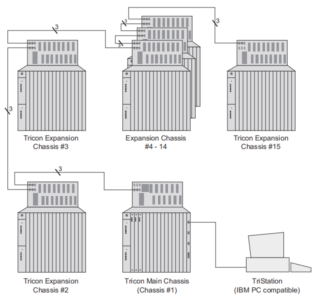
A Tricon controller can include a maximum of 15 chassis, housing any appropriate combination of input, output, communication, interface, and hot-spare modules. There are three types of chassis: Main, Expansion, and RXM.
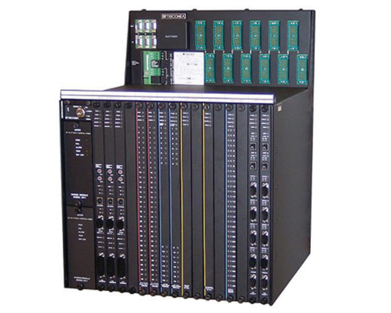
The Main Chassis houses the Main Processor modules and I/O modules. The Model 8110 Main Chassis houses up to six slot sets of I/O modules and the Model 8120E Enhanced Performance Main Chassis houses up to five sets of I/O modules. The I/O modules in a chassis are connected via I/O expansion bus ports that are triplicated RS- 485 bi-directional communication ports.
An Expansion Chassis (chassis 2 to 15) houses up to eight slot sets of I/O modules and HART™ Interface Modules. The Expansion Chassis connects to the Main Chassis by means of a triplicated RS-485 bi-directional communication port. Generally, the last Expansion Chassis must be located no more than 100 feet (30 meters) from the Main Chassis or an RXM Chassis.
An RXM Chassis houses a Primary or Remote RXM Module set and six slot sets of I/O modules. An RXM Chassis enables a system to extend to remote locations up to 7.5 miles (12 kilometers) from the Main Chassis, using SRXM modules.
TRICON SAMPLE CONFIGURATION:
MAIN PROCESSOR MODULES
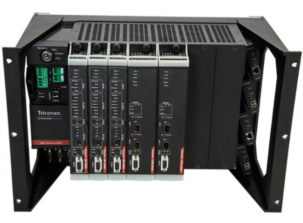
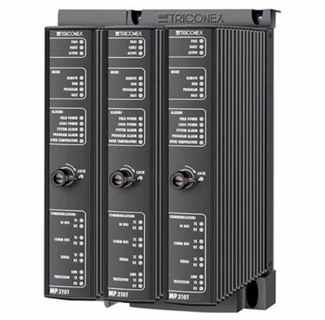
A Tricon controller contains three Main Processor modules. Each Main Processor controls a separate channel of the system and operates in parallel with the other Main Processors. A dedicated I/O Processor on each Main Processor manages the data exchanged between the Main Processor and the I/O modules. A triplicated I/O bus, located on the chassis backplane, extends from chassis to chassis by means of I/O bus cables.
Model 3009 Main Processors TRICONEX 3009 :Model 3009 has 256 MB DRAM (without battery backup) and 2 MB NVRAM (SRAM with battery backup).
Model 3009 Main Processors TRICONEX 3008 is a main processor module of the TRICONEX redundant fault-tolerant control system for industrial processes that require maximum safety and continuous production. The TRICONEX system has been successfully used in industries such as chemical, petroleum, natural gas, paper, and power generation to improve safety, increase production, and reduce downtime . The main processor module has a Motorola MPC860 32-bit, 50 MHz processor and 16 MB DRAM (without backup battery), 32 KB SRAM (with backup battery), and 6 MB flash PROM memory.
Model 3006 and 3007 Main Processors TRICONEX 3006 and TRICONEX 3007: Models 3006 and 3007 can be used with Tricon v9.0 to v9.5.x systems. They have the same architecture and specifications, except for SRAM, which is 2 megabytes for the 3006 and 1 megabyte for the 3007.
Modern industrial processes tend to be technically complex, involve substantial energies, and have the potential to inflict serious harm to persons or property during a mishap.
The IEC 61508 standard defines safety as “freedom from unacceptable risk.” In other words,
absolute safety can never be achieved; risk can only be reduced to an acceptable level.Safety methods to mitigate harm and reduce risk include:
• Changing the process or mechanical design, including plant or equipment layout
• Increasing the mechanical integrity of equipment
• Improving the basic process control system (BPCS)
• Developing additional or more detailed training procedures for operations and maintenance
• Increasing the testing frequency of critical components
• Using a safety-instrumented system (SIS)
• Installing mitigating equipment to reduce harmful consequences; for example, explosion walls, foams, impoundments, and pressure relief systems
SIS Factors
According to the ANSI/ISA S84.01 and IEC 61508 standards, the scope of an SIS is restricted to the instrumentation or controls that are responsible for bringing a process to a safe state in the event of a failure. The availability of an SIS is dependent upon:
• Failure rates and modes of components
• Installed instrumentation
• Redundancy
• Voting
• Diagnostic coverage
• Testing frequency
SIL Factors
An SIL can be considered a statistical representation of the availability of an SIS at the time of a process demand. A process demand is defined as the occurrence of a process deviation that causes an SIS to transition a process to a safe state.
An SIL is the litmus test of acceptable SIS design and includes the following factors:
• Device integrity
• Diagnostics
• Systematic and common cause failures
• Testing
• Operation
• Maintenance
In modern applications, a programmable electronic system (PES) is used as the core of an SIS.
The Tri-GP controller is a state-of-the-art PES optimized for safety-critical applications.
Safety Life Cycle Model
The necessary steps for designing an SIS from conception through decommissioning are described in the safety life cycle.
Before the safety life cycle model is implemented, the following requirements should be met:
• Complete a hazard and operability study
• Determine the SIS requirement
• Determine the target SIL
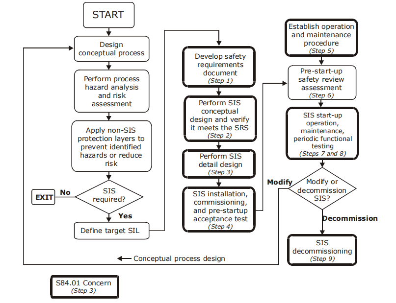
Developing an SIS Using the Safety Life Cycle
1 Develop a safety requirement specification (SRS).
An SRS consists of safety functional requirements and safety integrity requirements. An SRS can be a collection of documents or information.Safety functional requirements specify the logic and actions to be performed by an SIS and the process conditions under which actions are initiated. These requirements include such items as consideration for manual shutdown, loss of energy source, etc.
Safety integrity requirements specify a SIL and the performance required for executing SIS functions. Safety integrity requirements include:
• Required SIL for each safety function
• Requirements for diagnostics
• Requirements for maintenance and testing
• Reliability requirements if the spurious trips are hazardous2 Develop the conceptual design, making sure to:
• Define the SIS architecture to ensure the SIL is met (for example, voting 1oo1, 1oo2, 2oo2, 2oo3).
• Define the logic solver to meet the highest SIL (if different SIL levels are required in a single logic solver).
• Select a functional test interval to achieve the SIL.
• Verify the conceptual design against the SRS.
3 Develop a detailed SIS design including:
• General requirements
• SIS logic solver
• Field devices
• Interfaces
• Energy sources
• System environment
• Application logic requirements
• Maintenance or testing requirements
Some key ANSI/ISA S84.01 requirements are:
• The logic solver shall be separated from the basic process control system (BPCS).
• Sensors for the SIS shall be separated from the sensors for the BPCS.
• The logic system vendor shall provide MTBF data and the covert failure listing, including the frequency of occurrence of identified covert failures.
• Each individual field device shall have its own dedicated wiring to the system I/O. Using a field bus is not allowed!
• The operator interface may not be allowed to change the SIS application software.
• Maintenance overrides shall not be used as a part of application software or operating procedures.
• When online testing is required, test facilities shall be an integral part of the SIS design.
4 Develop a pre-start-up acceptance test procedure that provides a fully functional test of the SIS to verify conformance with the SRS.
5 Before startup, establish operational and maintenance procedures to ensure that the SIS functions comply with the SRS throughout the SIS operational life, including:
• Training
• Documentation
• Operating procedures
• Maintenance program
• Testing and preventive maintenance
• Functional testing
• Documentation of functional testing
6 Before start-up, complete a safety review.
7 Define procedures for the following:
• Start-up
• Operations
• Maintenance, including administrative controls and written procedures that ensure safety if a process is hazardous while an SIS function is being bypassed
• Training that complies with national regulations (such as OSHA 29 CFR 1910.119)
• Functional testing to detect covert faults that prevent the SIS from operating according to the SRS
• SIS testing, including sensors, logic solver, and final elements (such as shutdown valves, motors, etc.) 8 Follow management of change (MOC) procedures to ensure that no unauthorized changes are made to an application, as mandated by OSHA 29 CFR 1910.119.
9 Decommission an SIS before its permanent retirement from active service, to ensure proper review.
Applicable Industry
All Safety Systems
These general guidelines apply to all user-written safety applications and procedures:
• A design-change review, code-change review, and functional testing are recommended to verify the correct design and operation.
• After a safety system is commissioned, no changes to the system software (operating system, I/O drivers, diagnostics, etc.) are allowed without type approval and re�commissioning. Any changes to the application or the control application should be
made under strict change-control procedures. For more information on change-control procedures, see Project Change and Control on page 23. All changes should be
thoroughly reviewed, audited, and approved by a safety change control committee or group. After an approved change is made, it should be archived.
• In addition to printed documentation of the application, two copies of the application should be archived on an electronic medium that is write-protected to avoid accidental changes.
• Under certain conditions, a PES may be run in a mode that allows an external computer or operator station to write to system attributes. This is normally done by means of a communication link. The following guidelines apply to writes of this type:
— The communication link should use Modbus or other approved protocols with CRC checks.
— The communication link should not be allowed to write directly to output points.
— The application must check the value (of each variable written) for a valid range or limit before its use.
— For information on the potential impacts of writes to safety-related variables that result in disabling diagnostics such as Output Voter Diagnostics, see Module Diagnostics on page 36.
• PID and other control algorithms should not be used for safety-related functions. Each control function should be checked to verify that it does not provide a safety-related function.
• Pointers should not be used for safety-related functions. For TriStation 1131 applications, this includes the use of VAR_IN_OUT variables.
• An SIS PES should be wired and grounded according to the procedures defined by the manufacturer.
Emergency Shutdown Systems
The safe state of the plant should be a de-energized or low (0) state.
All power supplies should be monitored for proper operation.
Burner Management Systems
The safe state of the plant is a de-energized or low (0) state.
When a safety system is required to conform to the EN 50156 standard for electrical equipment for furnaces, PES throughput time should ensure that a safe shutdown can be performed within one second after a problem in the process is detected.
Fire and Gas Systems
Fire and gas applications should operate continuously to provide protection. The following industry guidelines apply:
• If inputs and outputs are energized to mitigate a problem, a PES system should detect and alarm open and short circuits in the wiring between the PES and the field devices.
• An entire PES system should have redundant power supplies. Also, the power supplies that are required to activate critical outputs and read safety-critical inputs should be redundant. All power supplies should be monitored for proper operation.
• De-energized outputs may be used for normal operation. To initiate action to mitigate a problem, the outputs are energized. This type of system shall monitor the critical output circuits to ensure that they are properly connected to the end devices.
Safety-Critical Modules
It is recommended that only the following modules be used for safety-critical applications:
• Main Processor Module
• Communication Module (only when using protocols defined for safety-critical applications)
• Analog Input Module
• Analog Input/Digital Input Module
• Analog Output Modules
• Digital Input Modules
• Digital Output Modules
• Pulse Input Module
The Solid-State Relay Output Module is recommended for non-safety-critical points only.
Safety-Shutdown
A safety application should include a network that initiates a safe shutdown of the process being controlled when a controller operates in a degraded mode for a specified maximum time. The Triconex Library provides two function blocks to simplify programming a safety-shutdown application: SYS_SHUTDOWN and SYS_CRITICAL_IO. To see the Structured Text code for these function blocks, see Appendix C, Safety-Critical Function Blocks. For more information on safety-shutdown networks, see Sample Safety-Shutdown Programs on page 49.
Response Time and Scan Time
Scan time must be set below 50 percent of the required response time. If scan time is greater than 50 percent, an alarm should be available.
Disabled Points Alarm
A project should not contain disabled points unless there is a specific reason for disabling them, such as initial testing. An alarm should be available to alert the operator that a point is disabled.
Disabled Output Voter Diagnostic
For safety programs, disabling the Output Voter Diagnostics is not recommended; however, if it is required due to process interference concerns, it can be done if, and only if, the DO is proof tested every three to six months.
Download All at Completion of Project
When development and testing of a safety application is completed, use the Download All command on the Controller Panel to completely re-load the application to the controller.
Modbus Master Functions
Modbus Master functions are designed for use with non-critical I/O points only. These functions should not be used for safety-critical I/O points or for transferring safety-critical data using the MBREAD and MBWRITE functions.
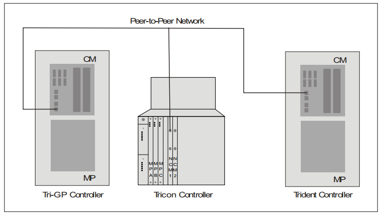
Triconex Peer-to-Peer Communication
Triconex Peer-to-Peer communication enables Triconex controllers (also referred to as nodes) to send and receive information. You should use a redundant Peer-to-Peer network for safety�critical data. If a node sends critical data to another node that makes safety-related decisions, you must ensure that the application on the receiving node can determine whether it has received new data.
If new data is not received within the time-out period (equal to half of the process-tolerance time), the application on the receiving node should be able to determine the action to take. The specific actions depend on the unique safety requirements of your process. The following sections summarize actions typically required by Peer-to-Peer send and receive functions.
Basic Triconex Peer-to-Peer Network
